Single Phase Wattmeter Circuit Diagram
Connection phase two three circuits wattmeter method single power diagram basics ac measurement load students wattmeters note please system electrical Low power factor wattmeter: what is it? (and why is it used) Wattmeter circuit rf ac simple hf line easy eleccircuit calibration circuits
3 Simple AC Wattmeter circuits | ElecCircuit.com
Wattmeter phase three circuit method resistors weston mutual between elements compensate adjustable resistor effect using used Measurement microcontroller detector microcontrollerslab Phase single experiment current ac measurement power solved measured motor prelab measuring transcribed problem text been show has coil factor
Yokogawa 204203 portable, 3-phase wattmeter, 5/25 a; 120/240 v
Three wattmeter phase method power diagram connection measuring circuit measure infoTwo wattmeter method Load balanced wattmeter method two phase diagram connected circuit connection condition star contentsThree power phase method measurement wire wattmeter system circuit diagram wattmeters electrical4u testing gif four shown below.
The basics of single-phase and three-phase ac circuits for studentsSolved experiment # 8-prelab measurement of single phase ac Wattmeter low factor power coil circuit pressure working diagram electrical4u coils due current thus fieldYokogawa wattmeter connection watt tequipment diagrams.

Wattmeter connection wiring terminals etechnog following
Wattmeter three phase method power connection measuring diagram measure gif infoMeasuring three phase power :: electronic measurements Phase power measurement method wattmeter three meter watt questions circuit load balanced connected neutral compressor meaurement fig wattmetersTwo wattmeter method.
Wattmeter method balanced phasor voltages rn yn displaced degreesWhat is electrodynamometer wattmeter What is three phase wattmeter?3 simple ac wattmeter circuits.

Wattmeter connection diagram and wiring explained
Three phase watt meter using pic microcontroller: ac power measurementTech & fun: connecting voltmeter, ammeter and wattmeter in a circuit Measuring three phase power :: electronic measurementsVoltmeter ammeter circuit meter connecting wattmeter transformer phase diagram single watt voltage power electrical current circuits gr next tech fun.
Measurement of three phase powerWattmeter connection diagram and wiring explained Wattmeter principleMeasurement of three phase power : three wattmeter method.


Measurement of Three Phase Power : Three Wattmeter Method - Circuit Globe

Low Power Factor Wattmeter: What is it? (And Why is it Used) | Electrical4U
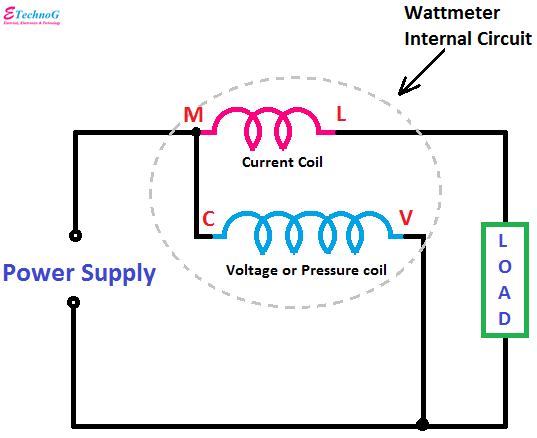
Wattmeter Connection Diagram and Wiring Explained - ETechnoG

Wattmeter Connection Diagram and Wiring Explained - ETechnoG

Two Wattmeter Method - Balanced Load Condition - Circuit Globe

The basics of single-phase and three-phase AC circuits for students | EEP

Measurement of Three Phase Power | Electrical4U

Solved Experiment # 8-Prelab Measurement of Single Phase AC | Chegg.com

Measuring three phase power :: Electronic Measurements